 Click for Larger
 |
 Click for Larger
 |
TR3 Wiring Lights
By Dan Masters
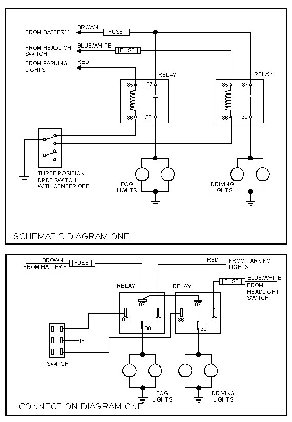
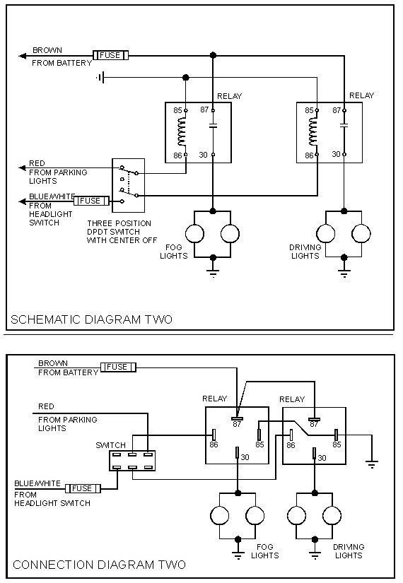
As promised, here is the schematic for the fog and driving light circuit I described on the Triumph Mail-List, along with a wiring/connection diagram as well. The wiring/connection diagram gives the physical details for wiring. Actually, I made two sets of diagrams; one switching the ground leads to the relays, and the other switching power to the relays. Functionally, the two circuits are the same, but one or the other will be easier to install, depending on where you mount the relays.
In general, you should choose the one that limits the length of the "powered" wires to the relay coil. That is, if you have the choice of long powered leads and short ground leads, or short powered leads and long ground leads, choose the location that gives the latter. A short on a ground wire will do no harm, whereas a short on one of the power leads can burn a wire or blow a fuse. It is always good practice to limit the exposure of wires that have power on them.
I used a double pole, double throw switch for both schemes, although you could get by with a single pole, double throw switch for circuit #1. The reason I did this is because that is the most likely type of switch you will find in the auto parts stores. If you can find a SPST switch, and prefer to use it, no problem at all - just ignore one half of the switch in the diagrams.
Some general comments on the installation:
1) The relay can be mounted any where that is convenient. The only criteria that is of any concern (other than protection from physical damage) is the TOTAL length of wire from the Brown wire to the relays and then from the relay to the lights. This length should be kept short, but as long as you use the proper size wire, it is not really important (assuming you don't intend to mount the relay in the trunk!).
2) The fuse in the lead to the Brown wire MUST be placed as close to the connection to the Brown wire as possible. If you do this, the remainder of the wire will be protected, and routing becomes less critical. Rather than connecting to an existing brown wire, I recommend using a new brown wire, and connecting it as close to the battery as you can. If you do connect to an existing brown wire, make sure it is large enough to handle the existing load as well as the added loads of the lights. HINT: If you detest unnecessary splices as much as I do, you might try this trick. I buy heavy-duty in-line fuse holders from the auto parts store and modify them to suit my purpose. I cut the leads off to about an inch and strip off all the insulation. Next, I remove the fuse contacts, and the wire, from the holder. I place the contacts in a vise and spread the wire strands out in a fan shape. Using a pair of needle nose pliers, I pull the center strand out of the crimp on the contact.
After a few of the center strands are removed, the rest come out easily. Once all the wires are removed, I spread the crimp just a little, and insert the end of the wire I wish to use and re-crimp, followed by soldering. This way, I get an in-line fuse holder with the correct color coded wires, and each wire long enough to reach the rest of the circuit without splices.
3) The wires used from the Brown wire to the relays and from the relays to the lights should be sized to carry the rated current of the lights with a little margin. I would use 12 gauge -- good for 20 amps -- unless you are using very powerful lamps. Remember, only one pair will be on at a time, so the wires should be sized for the most powerful pair.
4) The fuse MUST BE NO LARGER than the current rating of the smallest wires used in 3).
5) When you connect to the Red wire, you can use ANY Red wire you find, whichever of one is most convenient for you to connect to.
6) Use at least 14-gauge wire for the connections to the Red wire, and you won't need to use a fuse, as the Red wire is already fused.
7) The physical configuration of the DPDT switch as shown in the connection diagram is not important -- only that it looks like that shown when the wiring is completed. Wired one way, the FOG lights will be on with the switch handle in the up position: wired the other way, the DRIVING lights will be on with the switch handle in the up position.
8) The wires form the switch to the relays in scheme one can be just about any size you want, as they carry only the limited current of the relays. If one of these wires should short to ground, the effect will be exactly that of turning on the switch - no harm done.
9) The wires from the switch to the relays in scheme two must be sized carefully. Although they carry the same load as those in scheme one, since they are hot under certain conditions, a short here will blow a fuse, provided the wires are adequate to match the fuse. If the wires are too small, they may burn before the fuse blows. The red wire is fused at 17 amps, so the wire must be capable of handling 17 amps. Normally, that calls for 12 Ga., but you could get by with 14. The wire from the blue/white wire can be any size you wish, as long as the fuse is rated no larger than the wire can handle.
10) The colors for the wires shown are only for existing wires. Use any color you wish for the new wires.